Solenoid Controlled Pressure Reducing Control Valve is a hydraulic control valve that reduces the input pressure value to the desired pressure value. The control of the main valve is effected by solenoid coils mounted on it. The solenoid valve is provided with an electrical signal, a control device, a time relay, a switch, a PLC control unit, and control equipment. Thus, automation and control in application systems are easily achieved.
Coil Options
- Baccara 24 V AC
- Baccara 12 V DC Latch
- Burkert 24 V AC
Existing Diameters According To Their Connections
- Flanged: DN50, … , DN300
- Angled : 2″, DN50, DN80, DN100, DN150
- Threaded: 3/4″, 1″, 1¼”, 1½”, 2″, 2½”, 3″
- Victaulic : 2″, 3″, 4″, 6″

Operating Pressure |
Standart | 0,7 – 16 bar (10 – 240 psi) |
| Low Pressure Range | 0,5 – 10 bar (7,5 – 160 psi) | |
| High Pressure Range | 0,7 – 25 bar (10 – 360 psi) | |
Temperature |
Min. Operating Temperature | -10 °C (14 °F) DIN 2401/2 |
| Max. Operating Temperature | 80 °C (176 °F) DIN 2401/2 | |
Port |
Flanged | DIN 2501, ISO 7005 – 2 |
| Threaded | ISO (BSP) , ANSI (NPT) | |
Coating |
Standard | Epoxy |
| Optional | Polyester | |
Hydraulic Links |
Standard | Reinforced Nylon (Air Brake)) Hydraulic pipe SAE J 844 |
| Optional | Copper DIN 1057 | |
Actuator Type |
Single-Control Housing | Aperture Actuator, Aperture Off | |
Automatic control valves are used to perform the required operations as hydraulic with line pressure without the need for energy sources in the network line.

Valve Closing Mode
When the water pressure reaches the diaphragm, the water creates hydraulic force. This hydraulic force diaphragm, combined with the force applied by the spring creates a complete seal and allows it to close.

Valve Opening Mode
When the pilot on the main control valve in the closed position is placed in the evacuation position, pressurized water on the diaphragm of the main control valve is discharged. When the line pressure reaches the position to overcome the spring force, it applies hydraulic force from the bottom to the diaphragm of the control valve and allows the valve to reach the full open position

Modulation Mode
They are pilots connected to the control valve which enables the main valve to operate in this position. According to the amount of flow and pressure required to be adjusted, it controls the water pressure on the diaphragm continuously and allows it to operate in modulated position.
- Easy operation and maintenance with simple structure
- Low cost
- Working at wide pressure value range
- Perfect modulation even at low flow rates
- Continuous on / off with flexible aperture
- Full seal with reinforced diaphragm and inner spring
- Long life with epoxy-polyester coating
- Wide range of control area with the use of different pilot valves
- Ability to work in horizontal and vertical positions in application areas
inch |
mm |
inch |
mm |
inch |
mm |
inch |
mm |
inch |
mm |
inch |
mm |
inch |
mm |
inch |
mm |
inch |
mm |
|
|---|---|---|---|---|---|---|---|---|---|---|---|---|---|---|---|---|---|---|
Valve Diameter |
2 | 50 | 2½ | 65 | 3 | 80 | 4 | 100 | 5 | 125 | 6 | 150 | 8 | 200 | 10 | 250 | 12 | 300 |
CV m³/h @ 1 bar |
88 | 88 | 174 | 187 | 187 | 419 | 1139 | 1698 | 2276 | |||||||||
Kv gpm @ 1 bar |
102 | 102 | 201 | 216 | 216 | 484 | 1316 | 1961 | 2629 | |||||||||
KV: Valve flow Coefficient (Flow Rate At 1 Bar Pressure Loss M³/h @ 1 BAR)
CV: Valve flow Coefficient (Flow in pressure lossof 1 Psi GPM @ 1 Psi)
Q: Flow (M³/h, GPM)
ΔP: Pressure Loss (BAR, PSİ)
G: Specific Gravity of Water (For water = 1.0)
Installation
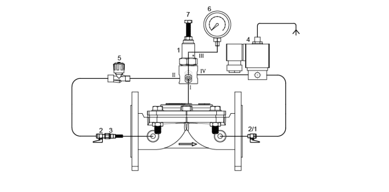
- The connection to the “II” output of the pressure reducing pilot is provided with the help of copper or plastic pipe after connecting to the valve Inlet, finger filter number 3 and mini ball valve number 2.
- The “I” output of the metal pilot is entered to the valve cover with the necessary connection elements.
- Valve output is connected to mini ball valve No. 2/1. Connection to the “IV” output of the metal pilot is provided from here. Finally, manometer is connected to the “III” output of the metal pilot.
- Valve rated diameter should be the same or a small rated diameter as the line diameter.
- In the direction of the arrow indicated on the valve Mount.
- Isolation valves (butterfly or sliding valve etc.) in the line Assembly of the valve.B) it is recommended to use air discharge valve, quick pressure discharge control valve (QR) and dirt retaining valves.
- Cavitation risk during pressure drop is dangerous for valve body. Adjust the output pressure value you want to adjust by looking at the cavitation chart or contact our company.
Adjusting
 Turn on the pump or turn on the mains main valve and give water to the system.
- Turn on the ball valve indicated by “2” and turn off the ball valve indicated by “2/1”.
- Wait for a while for water to reach the valve control chamber. When water reaches the control chamber, the manometer needle will show a certain pressure value.
- Set the desired output pressure value by looking at the manometer with the adjustment Bolt indicated by “6” on pilot valve indicated by “1”.
- When you turn the adjustment screw clockwise, the output pressure value will increase in the opposite direction when you turn the output pressure value will decrease.
- After adjusting the desired output pressure value, tighten the Contra nut under the adjustment Bolt. Turn on the ball valve indicated by “2” and give water to the system. After opening valve “2/1”, the manometer will display a value of zero.
- Check the output pressure value continuously. If Valve does not perform regulation, contact our company.
- Pressure Lowering Pilot
- Mini Ball Valve
- Finger Filter
- Solenoid Valve
- Manometer
- Pressure Adjustment Bolt
Installation
- After connecting to Valve Inlet, finger filter number 3 and mini ball valve number 2, connection to solenoid pilot’s “I” outlet and 3-way valve’s “C” outlet is provided with copper or plastic pipe.
- Solenoid pilot’s “II” number is connected to the auto “A” output of 3-way valve.
- Valve outlet” 4 ” is connected to the blind.
- Valve rated diameter should be the same or a small rated diameter as the line diameter.
- In the direction of the arrow indicated on the valve Mount.
- Isolation valves (butterfly or sliding valve etc.) in the line Assembly of the valve.B) it is recommended to use air discharge valve, quick pressure discharge control valve (QR) and dirt retaining valves.
- Cavitation risk during pressure drop is dangerous for valve body. Adjust the output pressure value you want to adjust by looking at the cavitation chart or contact our company.
Adjusting
 Connect the solenoid pilot valve wiring indicated by “5” to the control device.
- Turn on the pump or turn on the mains main valve and give water to the system.
- Open ” 2 ” spherical valve at Valve entrance • Then turn the three-way selector valve indicated by “1” on the valve to “auto” position.
- Pressure Lowering Pilot
- Mini Ball Valve
- Finger Filter
- Solenoid Valve
- Needle Valve
- Manometer
- Pressure Adjustment Bolt
FLANGED |
||||||||||
|---|---|---|---|---|---|---|---|---|---|---|
Available Diameters |
mm | 50 | 65 | 80 | 100 | 125 | 150 | 200 | 250 | |
| inch | 2 | 2½ | 3 | 4 | 5 | 6 | 8 | 10 | ||
 |
||||||||||
Port |
Flanged | |||||||||
Material |
GG25 – GGG40 | |||||||||
Body |
Globe | |||||||||
Transmission Pressure |
PN10 – PN16 – PN25 | |||||||||
VICTAULIC |
|||||||||
|---|---|---|---|---|---|---|---|---|---|
Available Diameters |
mm | 50 | 65 | 80 | 100 | 150 | |||
| inch | 2 | 2½ | 3 | 4 | 6 | ||||

|
|||||||||
Port |
Victaulic | ||||||||
Material |
GG25 – GGG40 | ||||||||
Body |
Globe | ||||||||
Transmission Pressure |
PN10 – PN16 – PN25 | ||||||||
THREADED |
|||||||||
|---|---|---|---|---|---|---|---|---|---|
Available Diameters |
mm | 25 | 40 | 50 | 65 | 80×50 | 80 | ||
| inch | 1 | 1½ | 2 | 2½ | 3x2x3 | ||||
 |
|||||||||
Port |
Threaded | ||||||||
Material |
GG25 – GGG40 | ||||||||
Body |
Globe | ||||||||
Transmission Pressure |
PN10 – PN16 – PN25 | ||||||||
ANGELED |
|||||||||
|---|---|---|---|---|---|---|---|---|---|
Available Diameters |
mm | 50 | 80 | 100 | 150 | ||||
| inch | 2 | 3 | 4 | 6 | |||||
 |
|||||||||
Port |
Flange – Threaded | ||||||||
Material |
GG25 – GGG40 | ||||||||
Body |
Globe | ||||||||
Transmission Pressure |
PN10 – PN16 – PN25 | ||||||||